This article is intended for those who are interested in basic electrical theory. The first part reviews the laws of series and parallel circuits. The second part explains the series-parallel circuit.
A Review: The Laws Of Series Circuits
In a series circuit containing two resistors and powered by a battery, only one electrical path exists from the plus terminal of the battery to the minus terminal of the battery and that path goes through both resistors. If you disconnect one resistor, you will have an open circuit and no current will flow through the other resistor.
Here are the rules for solving problems in a series circuit:
1) The sum of the voltage drops across the resistors is equal to the voltage of the battery. If you have two resistors in series, then the battery voltage is the sum of the voltage across each resistor.
2) The total resistance is the sum of the resistances.
3) The current is the same in a series circuit. There is only one electrical path. Therefore there is only one current and that current flows through both resistors.
4) The total power dissipated is the sum of the power dissipated in each resistor.
5) The voltage across any resistor equals the current through that resistor multiplied by the resistance of that resistor. This is an application of ohms law.
6) The battery voltage equals the current multiplied by the total resistance.
A Review: The Laws Of Parallel Circuits
In a parallel circuit containing two resistors and powered by a battery, two electrical paths exist from the plus terminal of the battery to the minus terminal of the battery. One electrical path goes through the first resistor and the other electrical path goes through the second resistor.
Here are the rules for solving problems in a parallel circuit:
1) The voltage drop across each resistor equals the battery voltage.
2) The total resistance in a parallel circuit containing two resistors is:
1/Rt = 1/R1 + 1/R2
where
Rt is the total resistance
R1 is the first resistor
R2 is the second resistor
3) The total current is the sum of the currents through each resistor. In a parallel circuit containing two resistors and powered by a battery, there are two electrical paths from the positive terminal of the battery to the negative terminal of the battery. The current splits: Part of the current takes one electrical path and part of the current takes the other electrical path.
4) The total power dissipated is the sum of the power dissipated in each resistor.
5) The voltage across any resistor equals the current through that resistor multiplied by the resistance of that resistor. Since both resistors are directly across the battery, the voltage across each resistor is the same as the battery voltage.
6) The source voltage equals the total current multiplied by the total resistance.
The Series-Parallel Circuit
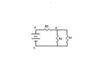
Now let’s examine the circuit of figure one. In the figure, there is one battery and three resistors.
Look at resistor R1. There is only one electrical path from point A to point B and that electrical path is through R1. If we remove R1, there is no electrical path from point A to point C. Therefore, R1 must be in series with the other resistors in the circuit.
There are two electrical paths between point B and point C. One electrical path goes through R2 and the other electrical path goes through R3. Therefore R2 must be in parallel with R3.
R1 is in series with the parallel combination of R2 and R3.
The current flows through R1 and then splits. Part of the current flows through R2 and the other part of the current flows through R3. Hence, the current through R1 equals the sum of the currents through R2 and R3.
The voltage across R2 equals the voltage across R3 because R2 and R3 are in parallel. The battery voltage equals the voltage across R1 plus the voltage across the parallel combination of R2 and R3.
To solve for the total resistance, first calculate the resistance of the parallel combination of R2 and R3.
The resistance of the parallel combination of R2 and R3 is Rp.
Rp = (R2*R3)/(R2 + R3)
Figure Two shows the equivalent circuit with R1 and Rp.
R1 and Rp are in series. Therefore, the total resistance (Rt) is the sum of R1 and Rp.
Now that we have the total resistance, we can calculate the total current. The total current (It) is equal to the battery voltage (Vt) divided by the total resistance Rt.
It = Vt/Rt
Now we can calculate the voltage across R1. The voltage across R1 equals the product of current through R1 and the resistance of R1.
V1 is the voltage across R1.
V1 = It * R1
The voltage across Rp equals the product of the current through Rp and the resistance of Rp
Vp is the voltage across Rp.
Vp = It * Rp.
Now we can solve for the current through R2. The voltage across R2 is Vp.
The current through R2 is I2
I2 = Vp/R2
Likewise, the current through R3 is I3
I3 = Vp/R3.
The current through R1 is equal to the sum of the currents through R2 and R3..
It = I2 + I3
This concludes the discussion of series-parallel circuits. The next article will show solutions to problems in series-parallel circuits.
References:
I have a Bachelor of Science in Electrical Engineering
Introductory Circuit Analysis Third Edition
ISBN 0-675-8559-4