This article assumes the reader has knowledge in the following areas:
Ohm’s Law
Series Circuits
Parallel Circuits
Series Parallel Circuits
Alternating Current (AC)
Trigonometry
Inductive Reactance
Capacitive Reactance
Impedance
When we discussed DC circuits, we assumed a constant voltage output from a DC source. In this discussion our voltage source outputs a sine wave with equal positive and negative peak voltages.
The reader could review inductive reactance, capacitive reactance and impedance in my article at
http://www.associatedcontent.com/article/1594075/capacitive_and_inductive_reactance.html?cat=58
The sine wave
The typical sine wave output could be described by the following formula
v = Vp * sin (wt)
where
v is the instantaneous voltage
Vp is the peak voltage of the sine wave
w is equal to 2*pi*F
pi equals 3.14
F is the frequency of the sine wave
t is the time period
The unit of measurement of the product w*t is the radian.
Likewise the equation for the current is
i = Ip * sin (wt)
where
i is the instantaneous voltage
Ip is the peak current of the sine wave
1) The resistor
Consider an AC circuit containing one resistor.
The instantaneous voltage v is equal to
v = Vp * sin (wt)
Then the instantaneous current i would be equal to
i = Ip * sin (wt)
2) The capacitor
Consider an AC circuit containing one capacitor.
The instantaneous voltage v is
v = Vp * sin (wt)
The instantaneous current i is
i = Ip * sin (wt + 90o)
Let’s figure out what this means in terms of the relation between voltage and current.
We define the time t = 0 as the instant that the voltage is at zero volts.
Assume that
Vp = 1 volt
Ip = 1 ampere
If t = 0, then w*t = 0 and
v = Vp * sin 0 = 0 volts
The current I is
i = Ip * sin (wt + 90) = Ip * sin 90 = Ip * 1 = Ip.
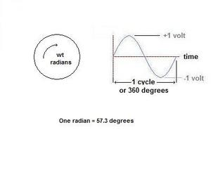
Look at figure one. It shows an AC sine wave and relates it to a circle. One cycle of the sine wave represents 360 degrees of the circle.
Figure two shows the relation between the voltage and current for an AC circuit containing a capacitor. The current leads the voltage by 90 degrees.
Hence the instantaneous current is at its maximum value when the instantaneous voltage is zero volts.
3) The inductor
Consider an AC circuit containing one inductor.
The source voltage v is
v = Vp * sin (wt)
Assume that
Vp = 1 volt
Ip = 1 ampere
At t = 0, the current is 0 amps.
i = Ip * sin (wt) = Ip * sin 0 = 0 amps
v = Vp * sin(wt + 90) = Vp * sin 90 = Vp * 1 = Vp
Figure three shows the relation between the voltage and current for AC circuit containing an inductor. The voltage leads the current by 90 degrees.
4) A resistor and a capacitor in series
In a series circuit containing a resistor and a capacitor, we are dealing with impedance Zt
The total impedance Zt is
Zt = R – 1/(jwc)
and
arc tan (1/jwc/r) = arc tan (Xc/R)
Assume that
Vp = 1 volt
Ip = 1 ampere
Now if v = Vp sin (wt)
then
i = Ip sin (wt + arc tan (Xc/R) )
The current leads the voltage by the angle
O = arc tan (Xc/R)
5) A resistor and an inductor in series
In a series circuit containing a resistor and a inductor, we are dealing with impedance Zt
The total impedance Zt is
Zt = R + jwL
and
arc tan (jwL/r) = arc tan (XL/R)
Assume that
Vp = 1 volt
Ip = 1 ampere
Now if i = Ip* sin (wt)
then
v = Vp sin (wt + arc tan (XL/R) )
The voltage leads the current by the angle
O = arc tan (XL/R)
5) A Resistor and a Capacitor in Parallel
The total impedance is
Zt = R*jXc/(R-jXc)
The current leads the voltage by the angle
O = arc tan (Xc/R)
6) A Resistor and an Inductor in Parallel
The total impedance is
Zt = R*jXL/(R+jXL)
The voltage leads the current by the angle
O = arc tan (XL/R)
7) A resistor, inductor and capacitor in series
Consider a circuit with a resistor, a capacitor and an inductor in series. Assume that the inductive reactance is greater than the capacitive reactance.
The total impedance is
Zt = R + j(XL – Xc)
and
O = arc tan ((XL-Xc)/R)
Assume that
Vp = 1 volt
Ip = 1 ampere
Now if i = Ip* sin (wt)
then
v = Vp sin (wt + arc tan ((XL-Xc)/R) )
The voltage leads the current by the angle
O = arc tan ((XL-Xc)/R)
The voltage leads the current because the inductive reactance is greater than the capacitive reactance.
Now lets repeat the above exercise assuming that the capacitive reactance is greater than the inductive reactance.
The total impedance is
Zt = R + j(XL – Xc)
and
O = arc tan ((XL-Xc)/R)
Assume that
Vp = 1 volt
Ip = 1 ampere
Now if v = Vp sin (wt)
then
i = Ip sin (wt + arc tan ((XL-Xc)/R) )
The voltage lags the current by the angle
O = arc tan ((XL-Xc)/R)
The current leads the voltage because the capacitive reactance is greater than the inductive reactance.
8) A resistor, inductor and capacitor in parallel
Consider a parallel circuit containing a resistor, an inductor and a capacitor. Assume that the inductive reactance is greater than the capacitive reactance.
The total impedance is
1/Zt = 1/R + 1/jXL + 1/(-jXc)
In polar coordinates this equation is
1/(Zt/O) = 1/R + 1/XL/90 + 1/Xc/-90
Since the inductive reactance is greater than the capacitive reactance, the net reactance is inductive and the phase angle is
O = arc tan ((XL-Xc)/R)
Therefore the voltage leads the current by the angle
O = arc tan ((XL-Xc)/R)
If the capacitive reactance is greater than the inductive reactance in the above exercise, the phase angle would be
O = arc tan ((XL-Xc)/R)
Therefore the voltage lags the current by the angle
O = arc tan ((XL-Xc)/R)
This concludes this article on AC analysis.
References:
I have a Bachelor of Science in Electrical Engineering
Introductory Circuit Analysis Third Edition
ISBN 0-675-8559-4