This article covers resistors, capacitors and inductors in AC circuits.
It assumes that the reader knows the following:
- Ohm’s Law
- Nature of Alternating current (AC)
- Series Circuits
- Parallel Circuits
- Capacitors
- Inductors
- Basic Trigonometry
- Algebra
As discussed in my article on the nature of alternating current, the voltage and current from an AC source are constantly changing. This means that any capacitor in the AC circuit is constantly charging or discharging. So, unlike in DC circuits sourced by a battery, the capacitor never looks like an open circuit.
CAPACITIVE REACTANCE
Capacitive reactance is the opposition to the flow of AC due to capacitor(s) in a AC circuit. Capacitive reactance is measured in ohms. Capacitive reactance is inversely proportional to the frequency and the value of capacitance.
The formula of capacitive reactance is:
Xc = 1/(2*pi*frequency*capacitance)
where
Xc is capacitive reactance in ohms
Pi is a constant.
Pi = 3.14
Frequency is the frequency of the alternating current
Capacitance is the value of the capacitor in farads.
INDUCTIVE REACTANCE
Likewise, inductive reactance is the opposition to the flow of AC due to inductor(s) in an AC circuit. Inductive reactance is measured in ohms and is directly proportional to the frequency and the value of inductance.
The formula for inductive reactance is
XL= 2*pi*frequency*inductance
Where XL is the inductive reactance.
Inductance is the value of the inductor in henries.
IMPEDANCE
The total opposition to the flow of alternating current is called impedance.
Ohm’s law in a DC circuit is
E = I * R
Ohm’s law in an AC circuit is
E = I * Z
where Z is the impedance.
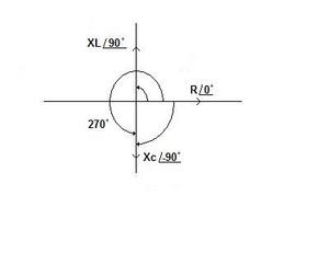
VECTOR DIAGRAMS OF CAPACITIVE REACTANCE, INDUCTIVE REACTANCE AND RESISTANCE
Each one of the quantities (R, Xc and XL) can be considered a vector. A vector has a magnitude and an angle associated with it.
Figure one shows the vector diagram. The resistance vector has an angle of zero degrees associated with it and is our reference for the angle of other vectors.
Going counterclockwise from the resistance vector to the inductive reactance vector, the angle between the resistance and the inductive reactance is 90 degrees.
Going counterclockwise from the resistance vector to the capacitive reactance vector, the angle between the resistance and the capacitive reactance is 270 degrees.
Going clockwise from the resistance vector to the capacitive reactance vector, the angle between the resistance vector and the capacitive reactance vector is -90 degrees.
The angle between the impedance vector and the resistance vector is needed for resolving AC circuit problems.
That angle is equal to the arctangent of the reactance divided by the resistance.
angle O = arctan(X/R)
We use the variable j to denote that the reactance vector does not lie along the horizontal axis.
Hence we have to note the angle as well as the magnitude of the vector.
The format is:
impedance magnitude /impedance angle
AC CIRCUIT CONTAINING ONE COMPONENT
If an AC circuit contains a capacitor, then the impedance is equal to the capacitive reactance.
Zt /-90o = -jXc
example
If an AC circuit contains an inductor, then the impedance is equal to the inductive reactance
Zt /90o = jXL
example
If an AC circuit contains resistor, then the impedance equals the resistance
Zt /0o = R
AC SERIES CIRCUITS
To solve problems in a AC series circuit, we need to understand the relation between capacitive reactance, inductive reactance and resistance. The three quantities can not simply be added together.
RESISTOR AND CAPACITOR IN A SERIES CIRCUIT
Consider an AC series circuit containing a resistor in parallel with a capacitor.
In figure two, we see a graph showing capacitive reactance and resistance. Note that the capacitive reactance, resistance and impedance form a triangle.
We can use the Pythagorean theorem to determine the impedance.
Zt2 = R2 + Xc2
Zt /arctan(Xc/R) = (R – jXc)
where
j = the square root of -1.
Zt is the impedance
Arctan(Xc/R) is the angle between the impedance vector and the horizontal axis.
(Remember that the tangent of the angle between the impedance vector and the resistance vector is equal to the opposite side divided by the adjacent side)
If the capacitive reactance is 40 ohms, then it would be listed as
Xc = 40 /-90o
The capacitive reactance is also equal to Zt * sin O
The resistance is equal to Zt * cos O
where O is the angle between the resistance vector and the impedance vector
Xc = Zt * sin O
R = Zt * cos O
Zt /arctan(Xc/R) = (R – jXc)
A RESISTOR AND AN INDUCTOR IN A SERIES CIRCUIT
If an AC series circuit contains a resistor and an inductor then the total impedance is
Zt2 = R2 + XL2
where
XL = Zt * sin O
R = Zt * cos O
Zt /arctan(Xc/R) = (R + jXL)
A CAPACITOR AND AN INDUCTOR IN A SERIES CIRCUIT
In figure one and figure two, note that the capacitive reactance vector and the inductive reactance vector are in opposite directions. Hence the total reactance is the difference between the capacitive reactance and the inductive reactance.
If an AC series circuit contains a capacitor and an inductor then the total impedance is as follows:
If XL is greater than Xc then
Zt/90o = (XL – Xc)
If XL is less than Xc then
Zt/-90o= (Xc – XL)
A RESISTOR, A CAPACITOR AND AN INDUCTOR IN A SERIES CIRCUIT
Assume that an AC series circuit contains a resistor, a capacitor and an inductor.
If the inductive reactance is greater than the capacitive reactance then
Zt2 = R2 + (XL – Xc)2
Zt/O = R + j(XL-Xc)
where O is the angle between the resistance vector and the reactance vector
where O = arctan((XL-Xc)/R)
If the capacitive reactance is greater than the inductive reactance then
Zt2 = R2 + (Xc – XL)2
Zt/O = R – j(Xc – XL)
where O = arctan((Xc-XL)/R)
PARALLEL CIRCUITS
AC Parallel circuits that contain two components
The general formula for impedances in parallel is
1/Zt/O = 1/(Z1/O1) + 1/(Z2/O2)
where
O is the angle between the total impedance vector and the resistance vector
O1 and O2 are 0o for pure resistance, 90o for pure inductive reactance
and -90o for pure capacitive reactance.
ADDITION OF VECTORS
Assume the inductive reactance is greater than the capacitive reactance.
(Z1/O1) = R1 + jXL
(Z2/O2) = R2 – jXc
(Z1/O1) + (Z2/O2) = R1 + jXL + R2 – jXc = (R1 + R2) + j(XL – XC)
MULTIPLICATION OF VECTORS
(Z1/O1) * (Z2/O2) = (R1 + jXL) ( R2 – jXc) = R1*( R2 – jXc) + jXL*( R2 – jXc)
(Z1/O1) * (Z2/O2) = R1*R2 – R1*jXc + jXL*R2 – j2XL*Xc
(Z1/O1) * (Z2/O2) = R1*R2 + XL*Xc + j(R1*Xc + R2*XL)
DIVISION OF VECTORS
When we divide 1 by Z1, what happens to O1?
That could be resolved by the following algebraic manipulation:
1/j = (j/j) * (1/j) = j/j2 = j/(-1) = -j
Hence
1/(R + jXL) = R – jXL
(R – jXL) is the conjugate of 1/(R + jXL)
Thus the angle becomes negative!
So
1/(Z1/O1) = (1/Z1)/-O1
and
1/(Z2/O2) = (1/Z2)/-O2
A RESISTOR AND A CAPACITOR IN A PARALLEL CIRCUIT
If an AC circuit contains a resistor in parallel with a capacitor, then the total impedance is
1/Zt/O = 1/Z1/O1 + 1/Z2/O2
where
O is the angle between the total impedance vector and the resistance vector
O1 is the angle between the Z1 vector and the resistance vector
O2 is the angle between the Z2 vector and the resistance vector
Z1 is the resistance vector
O1 is 0o
Z2 is the capacitive reactance vector
O2 is -90o
AN INDUCTOR AND A RESISTOR IN A PARALLEL CIRCUIT
If an AC circuit consists of an inductor in parallel with a resistor, then the total impedance is
1/Zt/O = 1/Z1/O1 + 1/Z2/O2
where
O is the angle between the total impedance vector and the resistance vector
O1 is the angle between the Z1 vector and the resistance vector
O2 is the angle between the Z2 vector and the resistance vector
Z1 is the resistance vector
O1 is 0o
Z2 is the inductive reactance vector
O2 is 90o
INDUCTOR AND CAPACITOR IN A PARALLEL CIRCUIT
If an AC circuit consists of an inductor in parallel with a capacitor, then the total impedance is
1/Zt /O = 1/(Z1/O1) + (1/Z2/O2) = 1/(XL/90o) + 1/(Xc/-90o)
where
O is the angle between the total impedance vector and the resistance vector
O1 is the angle between the Z1 vector and the resistance vector
O2 is the angle between the Z2 vector and the resistance vector
Z1 is the inductive reactance vector
O1 is 90o
Z2 is the capacitive reactance vector
O2 is -90o
RESISTOR, INDUCTOR AND CAPACITOR IN A PARALLEL CIRCUIT
If an AC parallel circuit contains a resistor, an inductor and a capacitor, then the total impedance is
1/Zt = 1/(Z1/O1) + (1/Z2/O2) + 1/(Z3/O3) = 1/(XL/90o) + 1/(Xc/-90o) + 1/(R/0o)
where
O1 is the angle between the Z1 vector and the resistance vector
O2 is the angle between the Z2 vector and the resistance vector
O3 is the angle between the Z3 vector and the resistance vector
Z1 is the inductive reactance vector
O1 is 90o
Z2 is the capacitive reactance vector
O2 is -90o
Z3 is the resistance vector
This concludes this article. The next article will include problems and resolutions in AC circuits containing resistors, capacitors and inductors.
References:
I have a Bachelor of Science in Electrical Engineering
Introductory Circuit Analysis Third Edition
ISBN 0-675-8559-4