In an earlier article we discussed the suitability of certain size holes drilled vertically in a proposed wood beam. Suitability was evaluated by examining excess beam capacity against the loss in capacity caused by the holes. If the loss in capacity caused by a hole did not exceed the excess capacity of the beam, the hole was deemed `okay. In these lessons the excess capacity was `everywhere’ in the beam, so the holes could be `anywhere’.
Now we will look at proposed holes at particular points of interest in a beam. The approach will be essentially the same as before, except that we will calculate excess beam capacities at the particular hole locations (points of interest), not the excess capacity presumed for the whole beam. The motivation for this is that some regions of the beam have more excess capacity than others. And we may need that excess capacity!
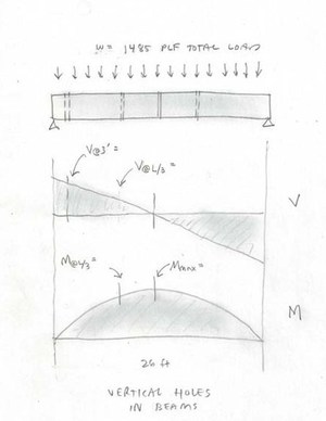
Consider a 6-3/4 inch (in.) x 24 in. timber roof beam spanning 26 feet (ft). It carries a uniformly distributed load of 1485 pounds per linear foot (plf), which includes snow, the dead weight of the roof, and the weight of the beam itself. We want to investigate the suitability of the following vertical holes:
1) a single vertical hole of ¾ in. diameter at beam midspan;
2) ¾ in. diameters holes at the third points along the beam (in case a single hole at midspan isn’t okay); and,
3) a 2 in. diameter hole 3 ft from one end.
Note, as before, that the vertical holes in this discussion are for `passage’ (only), say, of electrical wiring or whatever … not for bolts or other ways of transmitting significant structural loads.
In this example the Allowable Stresses for the beam are given to be:
Fb‘ = 2454 psi (Bending), and
Fv‘ = 305 psi (Shear).
Determination of these Allowable Stresses is complicated and is the topic of other articles; the determination of the applied stresses in the above beam is covered below.
The excess capacity at the various points of interest will be determined by comparing the applied stresses (shear and bending) to Allowable stresses. Further, any vertical hole must be at least 3 `hole diameters’ from the side faces of the beam, measured to the hole centerlines (regardless of the stresses).
As discussed previously, a limited number of relatively small holes do not affect beam deflections. Hence, our investigation will not include deflection calculations.
Let’s do it.
1) To determine the suitability of the single hole at the beam midspan, per American Institute of Timber Construction, Technical Note 19,
the effective size of the hole is 1.5 x ¾ in. = 1.125 in.
The corresponding loss of capacity at the section is
1.125 in. / 6.75 in. = 0.17 = 17%.
The bending stress at design load, fb, is
fb = M/S,
where M is the Bending Moment at midspan, and S is the section modulus.
From Figure 1 of the American Wood Council Design Aid No. 6, Beam Design Formulas with Shear and Moment Diagrams,
M = wL2/8 = 1485 plf (26 ft)2/8 = 125,485 lb-ft = 1,505,800 lb-in.
The Section Modulus is (without the hole)
S = bh2/6 = 6.75(24)2/6 = 648 in.3 (or we could have just looked it up, since the hole hasn’t been taken out yet).
Thus,
fb = M/S = 1,505,800 lb-in./648 in.3 = 2324 pounds per square inch (psi).
The ratio of design stress to the Allowable stress, at midspan, without the hole, is
2324 psi / 2454 psi = 0.95.
Thus, without the hole the beam has only 5% excess capacity at midspan; and since a hole of diameter ¾ in. will result in a loss of 17% capacity; the ¾ in. hole at midspan is NOT GOOD.
Let’s look for another region of the beam where, perhaps, there is more excess capacity, ideally enough to accommodate the hole.
So, instead of one light fixture at midspan, let’s try two fixtures (and accompanying vertical holes) … one at each of the third points along the beam.
2) To investigate the suitability of the holes at the third points we will look at both the shear and bending capacities. The capacity loss due to the holes at the third points will be the same as that for midspan (considering the same size holes); the excess capacities will be different.
From the Beam Design Formulas, Figure 1, the Shear force at the third point(s) is
V@L/3 = V@ 26/3 = V@ 8.67 ft = w (L/2 – x) = 1485 plf (26/2 – 8.67 ft) = 6430 lb.
The beam cross section area (without the hole) is A = b h = 6.75 x 24 = 162 in.2.
The Shear stress (without the hole) is, thus,
fv = (3/2)(V/A) = (3/2)(6430 lb / 162 in.2) = 60 psi.
The ratio of the design stress to Allowable is
60 psi / 305 psi = 0.20.
This means there is 80% excess shear capacity at the third point. A vertical hole only takes away 17%; so, with respect to shear, the hole is okay.
But now let’s look at bending.
The Bending Moment at the third point, again using Figure 1 of the Beam Design Formulas, is
M = w x (L – x )/ 2 = 1485 plf (8.67 ft)(26 – 8.67 ft)/2 = 111,540 lb-ft = 1,338,500 lb-in.
The Section Modulus (without the hole) is 648 in.3, from before.
Thus, at the third point(s),
fb = M/S = 1,338,500 lb-in./648 in.3 = 2066 psi.
The design stress over Allowable, fb/Fb‘, is
2066 psi / 2454 psi = 0.84.
The beam has 16% excess (bending) capacity at the third points; for the ¾ in. holes, 17% is needed; therefore, the ¾ in. holes at the third points are NOT GOOD.
(But only barely! … I’ll bet 5/8 in. holes will work at the third points.)
(I leave it up to you to prove that the 5/8 in. hole is `okay’ at the third point. Theoretically, the 3/4 in. hole will work if we move even a bit farther from the mispan, but may not be preferred in terms of light locations.)
3) To investigate the suitability of the 2 in. hole at a location 3 ft from one end, first, let’s make sure that size hole will even fit.
The distance from the center of the hole (assumed centered) to either face will be … 6.75 in. / 2 = 3.375 in.
In terms of `diameters’ this is 3.375 in. / 2.0 in. per diameter = 1.7 diameters. Since we need THREE diameters, the hole is way too big (or we need a way wider beam).
We don’t even need to deal with `capacity’ calculations for this size hole (in this size beam). Whatever was to pass through this 2 in. hole … needs to find some other way around the beam.
In summary, for this particular beam, the ¾ in. diameter holes are unsuitable at both midspan and third points, though, at the third points 5/8 in. diameter holes will probably work. The 2 in. diameter hole won’t work anywhere, regardless of capacity calculations; it is too (stinkin’) big, regardless.
References
Vertical Holes in Wood Beams, Jeff Filler, YAHOO! Voices.
Beam Design Formulas with Shear and Moment Diagrams, Design Aid No. 6, American Wood Council, Washington, DC, 2007.
Guidelines for Evaluation of Holes and Notches in Structural Glued Laminated Timber, Technical Note 19, American Institute of Timber Construction, Centennial, CO, July 2012.


 Holes in a Beam for Electrical Service")